- Diagram Frame is not shown by default due to automatic sizing, justification and routing functionality.
sdis the abbreviated diagram type (Show Abbreviated Type Property + Show Diagram Type Property)Interactionis the Context type (Show Context Type Property)DiagramNameis the Context Name (Show Context Name Property)DiagramNameis the Diagram Name (Show Diagram Name Property)- The Context (Type and Name) between Rhapsody and MagicDraw are different
- A SequenceDiagram is owned by an Interaction in MagicDraw
properties.ini file in the release folder includes a property setting to turn on and off the display of Execution Occurrences. SYSML_SEQUENCE_DIAGRAM.SHOW_ACTIVATIONSto false Default Setting
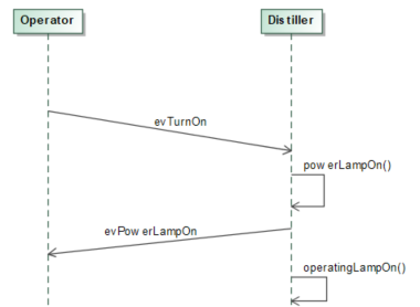
SYSML_SEQUENCE_DIAGRAM.SHOW_ACTIVATIONSto true
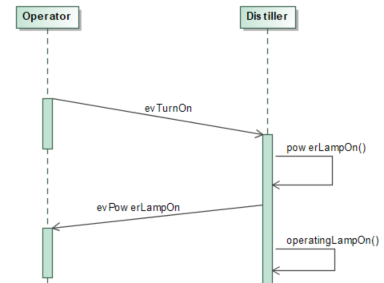
- When set to true some Message to self lines are distorted.
In Rhapsody, a
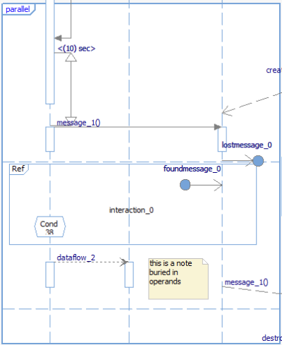
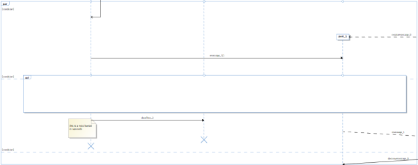
ref block shows all the elements in that area. In Magicdraw, a ref block hides every elements (such as ConditionMark, etc…) that are in the same area.
Rhapsody
MagicDraw
In Magicdraw, you can create a DurationConstraint only on prexisting elements, so it is drawn between two messages. Them we have the DurationConstraint constraining both messages.:
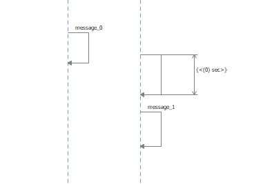
In Rhapsody, you can create a TimeInterval anywhere in the Sequence. It is not attached to a message, and can be drawn closed, or far from a message:
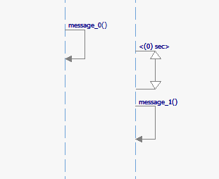
The Publisher will create a self message that will hold the DurationConstraint at the same position as the TimeInterval.