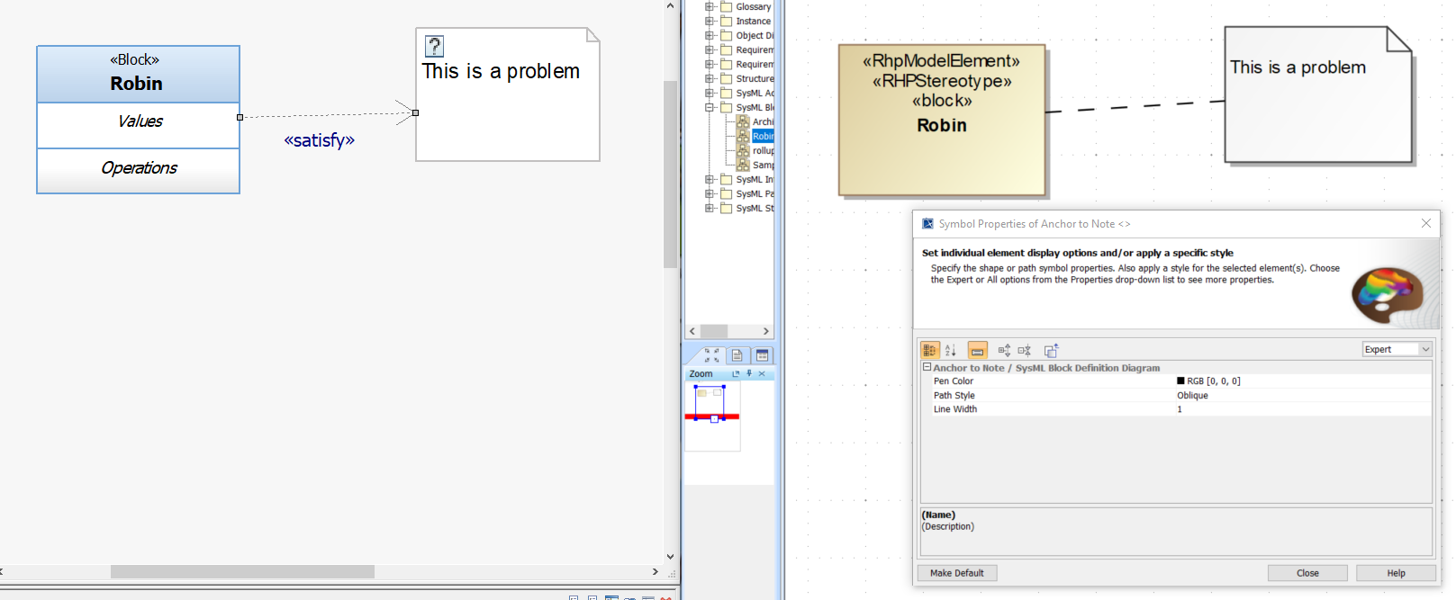
<<Satisfy>> Dependency to a Problem is transformed by the Publisher as an Anchor to a Note as shown in the figure below.
- The Parts have to be owned by a Block.
- The Constraint properties in the diagram have to be owned by the same Block.
- The Properties in the diagram have to be owned by the Block.
If ports are connected via Connector, both port types must be compatible and the connector ends need to be defined.
- When red connector lines are shown in the published model you can right click on the "Update Connector Ends" menu.
- Connection errors may also exist in Rhapsody prior to publish. Ensure the Connectors have defined Ends prior to publish.
- MagicDraw provides a Warning when the GraphEdge is not in the same direction as the Semantic Connector